

Concepts: magnetic flux, Faraday's law and Lenz's law
Electromagnetic Induction22 min readLesson 2 of 6
2.1 Magnetic flux
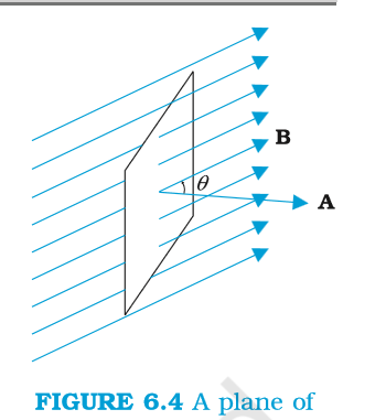
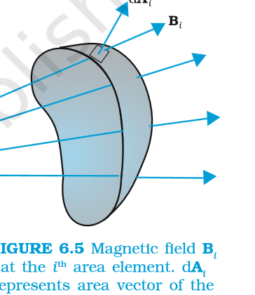
The magnetic flux through a surface measures how many field lines pass through it. For a plane area A in a uniform field B, the flux is phi = B A cos theta, where theta is the angle between the field and the area vector, which is normal to the surface. The area vector has the magnitude of the area and points along the normal. When the plane is perpendicular to the field the flux is maximum, BA, and when the plane is parallel to the field the flux is zero. For a curved surface or a field that varies from point to point, the surface is divided into small elements and the contributions are added, phi = sum of B_i dot dA_i. The unit of flux is the weber, which is one tesla metre squared, and flux is a scalar though it can be positive or negative according to the choice of normal.
2.2 Faraday's experiments
Faraday showed that a changing magnetic environment produces an emf in a circuit. Moving a magnet towards or away from a coil made a galvanometer deflect in opposite directions. Moving a current carrying coil towards or away from another coil did the same. Pressing a key to start a current in one coil produced a sudden kick in a neighbouring coil, and releasing the key gave a kick the other way. The common thread in every experiment is that the flux through the circuit was changing. A steady field, however strong, produces nothing; only change matters.
2.3 Faraday's law
Faraday's law states that the emf induced in a circuit equals the negative rate of change of magnetic flux through it. For a coil of N turns, each turn links the same flux, so the induced emf is minus N times the rate of change of flux. The law is often written with the flux linkage N phi in place of phi. The magnitude is what most numerical questions ask for, and the negative sign carries the direction, which is Lenz's law.
A useful way to read the law is to see the two ways the flux can change. The field itself can change with time, as when a current in a neighbouring circuit changes, and the area or its orientation can change, as when a loop is pulled out of a field or rotated. Both cases produce an emf, and the formula covers both because it only refers to the rate of change of flux, not to the reason for the change.
2.4 Lenz's law and conservation of energy
Lenz's law says that the induced current is in such a direction that the magnetic field it produces opposes the change in flux that caused it. If a magnet is pushed towards a coil, the coil produces a face that repels the approaching magnet, so the induced current's field points against the magnet's motion. If the magnet is pulled away, the coil produces a face that attracts it back. This opposition is exactly what conservation of energy requires: the mechanical work done in pushing the magnet against the repulsive force is what appears as the electrical energy in the coil. If the induced current instead aided the change, the magnet would accelerate without any work input and energy would be created from nothing.
2.5 Reading the direction
For a coil, the direction can be found in three steps. First decide whether the flux through the coil is increasing or decreasing. Second use Lenz's law to decide whether the induced field must oppose the external field or support it: oppose it when the flux is growing, support it when the flux is falling. Third use the right hand rule to turn the direction of the induced field into the sense of the current, with the thumb along the axis and the curled fingers along the current. For a conductor moving in a field, Flemming's right hand rule does the same job in one step.
A worked check makes it concrete. A circular coil sits in a field pointing into the page, and the field is switched off. The flux into the page is decreasing, so the induced current must produce a field into the page to oppose the decrease. The right hand rule then makes the current flow clockwise as seen from the reader's side. If instead the field is switched on and grows, the induced current runs anticlockwise, producing a field out of the page that opposes the growth.
Slideshow, slide 1 of 3. Use the left and right arrow keys to change slides and the space bar to play or pause.
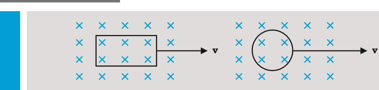
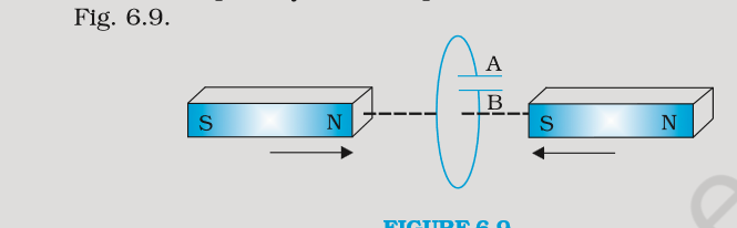
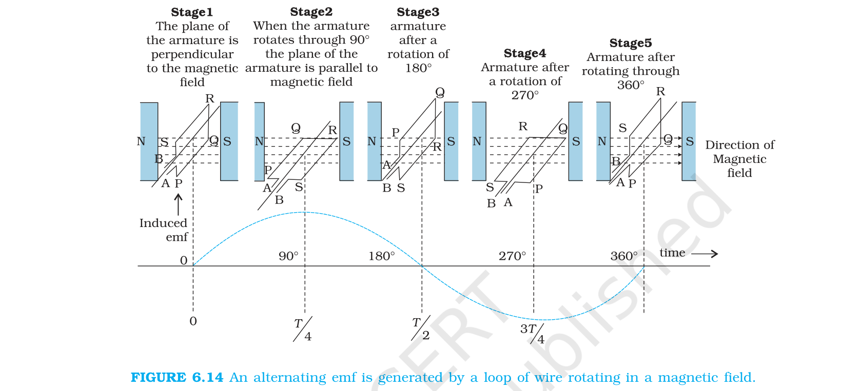
Figure 6.8 a square loop and a circular loop moving out of a region of magnetic field, used to compare how the induced emf varies with time.
2.6 Two standard checks
A coil of 100 turns and area 0.02 square metre sits with its plane perpendicular to a field of 0.5 T, and the field drops to zero in 0.1 s. The initial flux is 0.5 x 0.02 = 0.01 Wb and the final flux is zero, so the rate of change is 0.01/0.1 = 0.1 Wb per second, and the emf is 100 x 0.1 = 10 V. The direction follows from Lenz's law: the field through the coil is falling, so the induced field points the same way as the original field, and the current direction follows from the right hand rule.
A rectangular loop of side 0.2 m moves out of a field of 0.4 T at 0.5 m per second, with the side of length 0.2 m cutting the field lines. The motional emf is B l v = 0.4 x 0.2 x 0.5 = 0.04 V. If the loop resistance is 0.1 ohm, the current is 0.4 A and the power dissipated is I squared R = 0.016 W, which equals the mechanical power B squared l squared v squared / R.
- Can I write Faraday's law with the Lenz sign and explain the sign physically?
- Can I find the direction of induced current in a coil from the change in flux?
- Can I compute the emf for a coil rotating in a field and identify its peak value?