

Concepts: AC values, phasors and the three elementary circuits
Alternating Current22 min readLesson 2 of 6
2.1 AC voltage and rms values
An alternating voltage reverses direction periodically. In the standard form it is a sine wave, v = v_m sin omega t, with v_m the peak value and omega the angular frequency, related to the ordinary frequency by omega = 2 pi f. The current in a circuit driven by this source is in general i = i_m sin (omega t plus or minus phi), where phi is the phase difference between the voltage and the current.
The average of a sine wave over a full cycle is zero, so the average voltage is not useful for power. Instead the root mean square value is used: V_rms is the square root of the mean of v squared over a cycle, which comes out as v_m divided by the square root of two. For the 220 V, 50 Hz mains supply, 220 V is the rms value and the peak is 311 V. The rms value is also called the effective value because a resistor dissipates the same power with a steady voltage of V_rms as with the alternating voltage.
2.2 Phasors
A phasor is a rotating vector whose projection on a fixed axis gives the instantaneous value of a sinusoidally varying quantity. The length of the phasor represents the peak value and the angle with the reference axis represents the phase. Voltage and current phasors are drawn in the same diagram, and their relative angle is the phase difference. The phasor method turns the addition of sinusoids into ordinary vector addition, which is why the impedance of a series circuit is found by adding R, X_L and X_C as perpendicular components.
2.3 The resistor
For a resistor the current is i = (v_m / R) sin omega t, so the current and the voltage reach their peaks together and the phase difference is zero. The resistance R is the same for every frequency, the average power is V_rms I_rms and the power factor is one. A resistor converts electrical energy into heat, which is why the average power in this circuit is not zero.
2.4 The inductor
For an inductor the voltage is v = L di/dt. With a sinusoidal current the derivative shifts the phase by 90 degrees, and the result is that the current lags the voltage by pi by 2. The opposition to the current is the inductive reactance X_L = omega L, which rises with frequency. At very high frequency an inductor behaves almost like an open circuit, and at zero frequency, which is direct current, it behaves like a plain wire. The average power over a full cycle is zero, because the voltage and current are a quarter cycle apart: energy is stored in the magnetic field in one quarter and returned in the next.
2.5 The capacitor
For a capacitor the current is i = C dv/dt, and the derivative again shifts the phase, but this time the current leads the voltage by pi by 2. The opposition is the capacitive reactance X_C = 1/(omega C), which falls with frequency. At very high frequency a capacitor behaves almost like a short circuit, and for direct current it blocks the steady current once it is charged. Here too the average power over a full cycle is zero, with energy stored in the electric field and returned.
2.6 Reading the three circuits together
The three elementary circuits form a pattern that an examiner expects to see stated cleanly. In a resistor the phase difference is zero, the impedance is R, the average power is V_rms I_rms and the current follows the voltage instantly. In an inductor the phase difference is plus pi by 2 with the current lagging, the reactance is omega L and the average power is zero. In a capacitor the phase difference is minus pi by 2 with the current leading, the reactance is 1/(omega C) and the average power is zero. The reactances are not resistances: they depend on the frequency, and they describe the opposition that comes from the storage of energy in a field rather than from its dissipation as heat.
A useful check is to ask what each element does at the two extremes. For direct current, the inductor is a wire and the capacitor is an open circuit. For very high frequency alternating current, the inductor is almost an open circuit and the capacitor is almost a wire. This frequency behaviour is the basis of filters and of the tuning in a radio receiver.
Slideshow, slide 1 of 3. Use the left and right arrow keys to change slides and the space bar to play or pause.
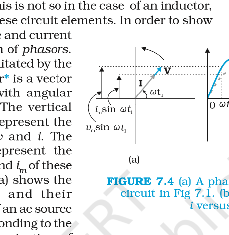
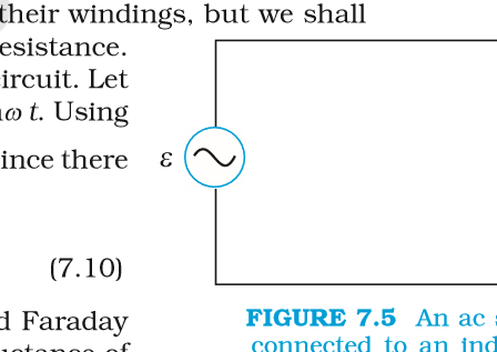
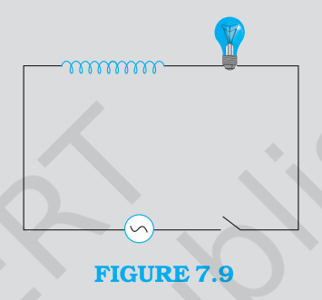
Figure 7.4 phasor diagram for a resistor circuit with the voltage and current phasors rotating together and the v and i graphs.
2.7 Two checks with numbers
A 220 V rms supply is connected to a 44 mH inductor at 50 Hz. The angular frequency is 314 rad per second, so X_L = 314 x 0.044 = 13.8 ohm, and the rms current is 220/13.8 = 15.9 A. The same supply across a 60 microfarad capacitor gives X_C = 1/(314 x 60 x 10^-6) = 53.1 ohm and a current of 4.1 A. Both circuits have zero average power, so the product V I is not the power; it is the reactive power that sloshes back and forth.
A 100 W resistor connected to 220 V, 50 Hz draws I_rms = P/V = 0.45 A, and the peak current is 0.64 A. The power of 100 W is consumed as heat, unlike the reactive circuits above.
- Can I convert between peak and rms values and state why rms is used for power?
- Can I state the phase relation and reactance for R, L and C separately?
- Can I explain why the average power in a pure L or C circuit is zero?