

Series LCR circuit, resonance, power and the transformer
Alternating Current24 min readLesson 3 of 6
3.1 The series LCR circuit
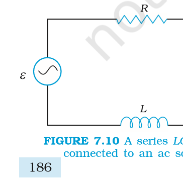
With a resistor, an inductor and a capacitor in series, the same current flows through all three, and the voltage across the combination is the phasor sum of the three voltages. The voltage across the resistor is in phase with the current, the voltage across the inductor leads the current by 90 degrees and the voltage across the capacitor lags by 90 degrees. Because the inductive and capacitive voltages are opposite, they partly cancel, and the resultant voltage is the sum of the resistor voltage in phase and the net reactive voltage at right angles to it. The result is an impedance Z which is the square root of R squared plus (X_L minus X_C) squared, and a phase angle with tan phi equal to (X_L minus X_C) divided by R.
The current amplitude is v_m/Z. When the circuit is inductive, with X_L greater than X_C, the current lags the voltage; when it is capacitive, the current leads. The impedance is never less than R, and it equals R only at resonance.
3.2 Resonance
A series LCR circuit is at resonance when the inductive reactance equals the capacitive reactance, which happens at the angular frequency omega_0 = 1 divided by the square root of L C. At this frequency the two reactances cancel, the impedance becomes R and the current amplitude reaches its maximum, v_m/R. The circuit behaves as if it were purely resistive, the voltage and current are in phase and the power factor is one. The resonant frequency depends only on L and C, not on R, while the sharpness of the resonance does depend on R: a smaller resistance gives a sharper peak in the current frequency graph and a larger quality factor. The quality factor Q = omega_0 L / R measures this sharpness, and high Q means a narrow, tall resonance peak.
This is the basis of tuning: a radio receiver changes its capacitance or inductance so that its resonant frequency matches the frequency of the station to be received, and the current at that frequency is large compared with the others.
3.3 Power in an AC circuit
The instantaneous power in an AC circuit is the product of the instantaneous voltage and current, and its average over a full cycle is V_rms I_rms cos phi, where phi is the phase difference between voltage and current and cos phi is the power factor. In a pure resistor phi is zero and the power is V_rms I_rms. In a pure inductor or capacitor phi is 90 degrees and the average power is zero: the energy stored in the field in one quarter cycle is returned in the next. A circuit with both resistance and reactance has a power factor between zero and one, and the part of the current that does no work is I_rms sin phi, called the wattless current.
If the current lags the voltage the circuit is largely inductive and the power factor is lagging; if the current leads, it is largely capacitive and the power factor is leading. The power factor matters in power transmission because a low power factor means a large current for the same useful power, and the losses in the cables are proportional to the current squared.
3.4 LC oscillations
If a charged capacitor is connected across an inductor, the charge and current oscillate at angular frequency 1 divided by the square root of L C, with the energy passing back and forth between the electric field of the capacitor and the magnetic field of the inductor. In a real circuit the resistance damps the oscillation, and the energy eventually appears as heat. The same oscillation is the basis of receiving circuits.
3.5 The transformer
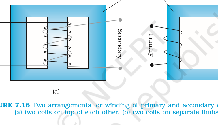
A transformer changes an alternating voltage from one value to another using mutual induction. Two coils, the primary with N_p turns and the secondary with N_s turns, are wound on a common soft iron core so that the flux generated by the primary links the secondary. If the primary is ideal and all the flux links both coils, the emf per turn is the same in both, so V_s/V_p = N_s/N_p. A step-up transformer has N_s greater than N_p and raises the voltage; a step-down transformer lowers it. For an ideal transformer with no losses the power is the same on both sides, so the currents are in the inverse ratio, I_s/I_p = N_p/N_s. A step-up transformer therefore raises the voltage and lowers the current, which is why power is transmitted at high voltage and low current: the loss in the cables is I squared R, so reducing the current cuts the transmission loss sharply.
A real transformer has losses. The copper windings have resistance, so I squared R loss appears in the coils. The iron core is repeatedly magnetised and demagnetised, which costs hysteresis energy. The changing flux also induces eddy currents in the core, and these are reduced by making the core from thin insulated sheets. Some flux leaks between the coils instead of linking both. Efficiency is the output power divided by the input power, and a good transformer reaches above 90 per cent.
Exam
In an LCR numerical, first compute X_L and X_C, then Z, then the current, then the power factor. Write the resonance condition separately, because a question can ask for the resonant frequency even when the circuit is driven at another frequency.