
Exercise practice 2: Exploring Some Geometric Themes
Exploring Some Geometric Themes28 min readLesson 4 of 8
4.1 Figure it Out, page 92: projections of lines and solids
Question 1. Observe the front, top and side views of the different lines. Is there any relation between their lengths?
Answer. For a line segment of true length l, each projection has length l cos θ, where θ is the angle between the line and that plane. Therefore p(front)² + p(top)² + p(side)² = l², and each projection is at most l. A projection equals l only when the line is parallel to the plane.
Key steps. Take the line's direction angles with the three planes. The three projections are the components of the same segment along three perpendicular directions, so their squares add to the square of the segment. This is the three-dimensional version of the Baudhayana theorem.
Question 2. Give the three views of this list of solids: pyramid, prism, cone, cylinder, parallelepiped, cuboid and cube.
Answer. Cube: three squares. Cuboid: three rectangles, sized by the three edge lengths. Parallelepiped: three parallelograms, generally different. Cylinder in the usual upright orientation: front and side rectangles, top a circle. Cone upright: front and side triangles, top a circle with a centre dot for the apex. Prism: two views rectangles, one view the polygon base (or a rectangle, depending on orientation). Pyramid: two views triangles, one view the polygon base with the apex at its centre.
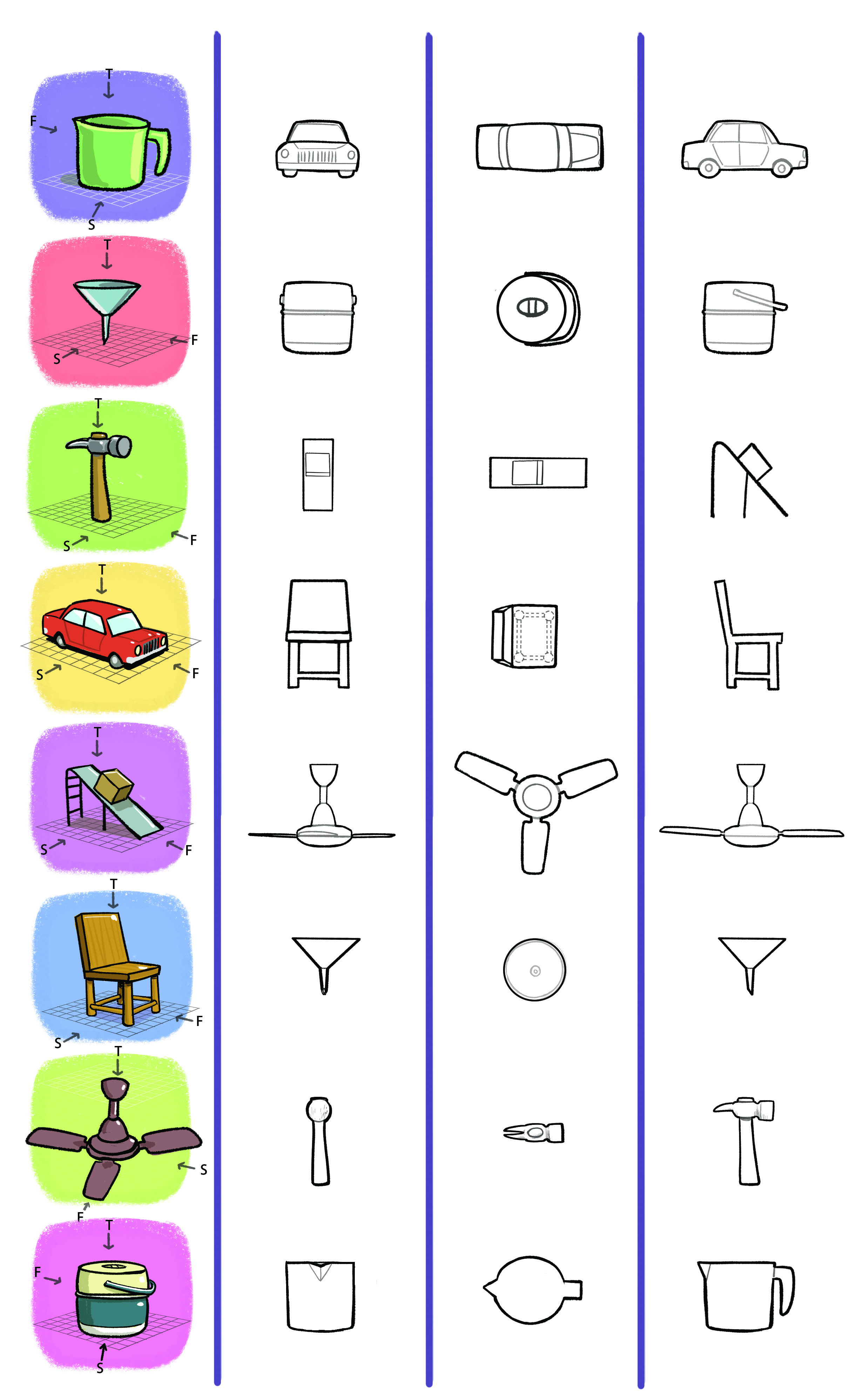
Question 3. Match each object with its projections.
Answer. The matching sheet shows eight objects on the left and three columns of outlines to their right; each horizontal row is one object's front, top and side view. Reading the rows from top to bottom, the matches are: car row 1; cooker row 2; slide row 3; chair row 4; ceiling fan row 5; cone row 6; hammer row 7; mug row 8. The mug is the clearest check: its front view is the plain cup outline, its top view is the round shape with the handle loop, and its side view shows the cup with its handle.
Key steps. For each object, draw the outline from the front, the outline from directly above, and the outline from the side. Match the three outlines as a set. If two objects share a view, use the distinguishing part, such as a handle or a wheel, to separate them.
Question 4. Build one solid from matching cubes so that it produces each of the nine pairs of views shown.
Answer. The projection sets fix how many cubes are visible in each row and column. Start from the top view, which shows the footprint of the solid, then choose heights so that the front and side views match. A top view square means at least one cube in that column; the front view tells the tallest stack in that column, and the side view tells the tallest stack in that row.
Key steps. Draw the top-view footprint and write the required maximum height in each column from the front view. Adjust the row maxima to satisfy the side view, then fill the remaining cubes only where they are hidden. Many projection sets have more than one solid, so give one valid construction and check it against all three views.
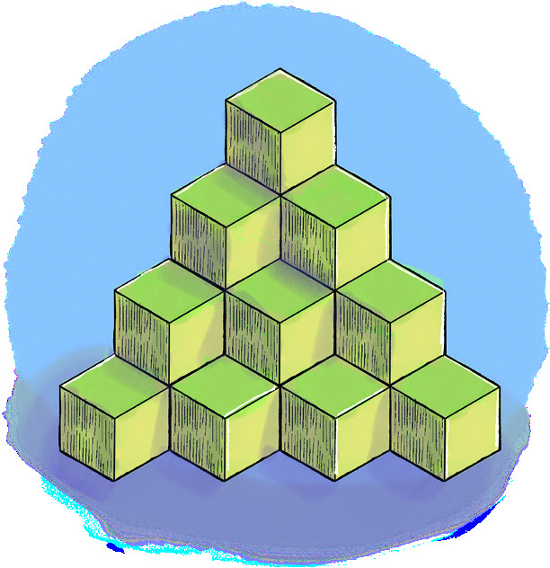
Question 5. Find the number of cubes in the stack shown.
Answer. The stack is a triangular pyramid of cubes: four cubes in the bottom row, three in the next, two above them, and one on top, so the total is 4 + 3 + 2 + 1 = 10 cubes.
Key steps. Count layer by layer. The bottom layer shows a triangular arrangement of 4 cubes, each higher layer has one fewer, and no cubes are hidden behind the visible ones in this stack. Adding the layers gives 10.
Question 6. What shapes can the projection of a cube make under different orientations?
Answer. The projection can be a square (face parallel to the plane), a rectangle (a face edge-on), a parallelogram or rhombus (two faces meeting at an edge), or a regular hexagon (the isometric orientation with a vertex towards the viewer). Degenerate orientations can give a line segment. The specific shape depends on the angle between the cube and the plane, not on the cube itself.
Key steps. Project the eight vertices and take the outline of the resulting set of points. Face-on, four vertices form a square. Tilt about one edge to get a rectangle. Tilt about a diagonal to get a hexagon, with two opposite vertices projecting to the extreme points. The outline is always a convex polygon with 4 or 6 sides.
4.2 Figure it Out, page 99: isometric drawings
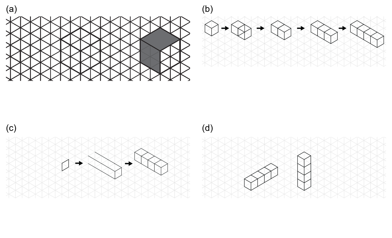
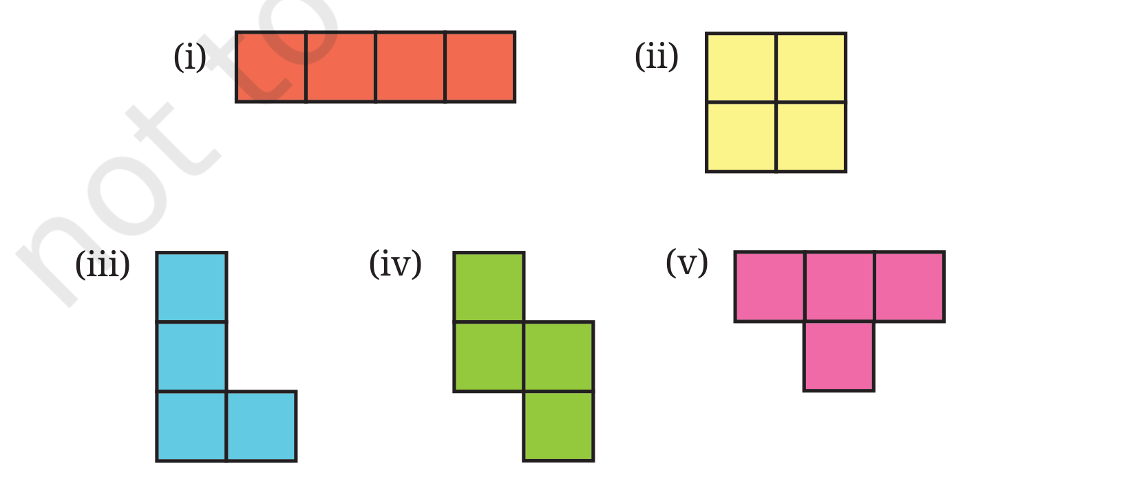
Question 1. Besides the five ways of gluing four cubes shown, are there other ways? Draw them.
Answer. Yes. There are 8 different free shapes made of four cubes joined face to face: the 5 flat arrangements (the straight row, the square, the L, the T and the zigzag) plus 3 genuinely three-dimensional arrangements. One example has three cubes in an L shape and the fourth cube on top of the corner cube.
Key steps. Build every arrangement from a 3-cube L and place the fourth cube in a new position that touches a face and is not a flat arrangement. Rotations and reflections count as the same shape. The extra three-dimensional shapes cannot be laid flat, which is why they do not appear among the five planar tetrominoes.
Question 2. Draw the given figures on the isometric grid.
Answer. Use the three grid directions as the three axes: the vertical lines are the height axis, and the two diagonal directions are the length and depth axes. For each cube edge, move one unit along the correct axis, in the positive or negative direction, and draw the segment. Hidden edges are drawn lightly or erased.
Key steps. Start at a visible corner. Count units along each axis before drawing. Follow the outline first, then add the depth edges. Check that parallel edges on the solid stay parallel on the grid, because projection sends parallel lines to parallel lines.
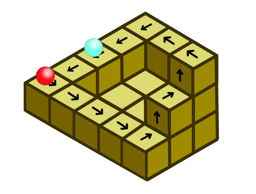
Question 3. What is strange about the path of the ball, and how do you recreate it on the isometric grid?
Answer. The path looks like a continuous downhill slope, but the direction of 'down' changes as the ball goes around. It is an impossible figure: locally each segment follows the grid directions, but a global rule would make the ball climb as well as fall. Recreate it by copying short physically realisable portions on the isometric grid and joining them, then note where the depth interpretation flips.
Key steps. Break the drawing into straight segments along the three isometric directions. For each segment, decide which of the three axes it uses. The pieces can each be drawn; the contradiction appears when they are interpreted as one 3D path.
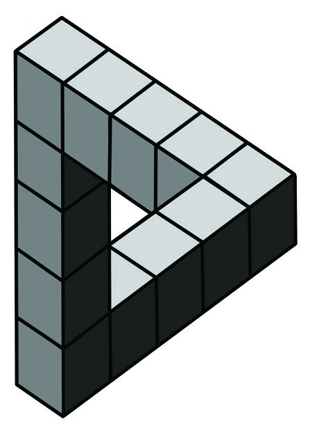
Question 4. Observe the impossible triangle. (i) Can a model be built from actual cubes? What are its front, top and side profiles? (ii) Recreate it on the isometric grid. (iii) Explain what makes the illusion convincing.
Answer. (i) No, a single physical model of the complete figure cannot be built from cubes. The front, top and side profiles of the drawing are rectangular outlines, but the connections that produce them are contradictory. (ii) Draw the three arms along the isometric axes, matching the outer edges, then join the corners with the staircase-like inner edges. (iii) The illusion works because a 2D projection discards depth. Each local part of the drawing is consistent, but the depth cues at the three corners cannot all be true at once, and the eye accepts the local parts before checking the global consistency.
Key steps. Draw the outer triangle first, then the inner staircase edges parallel to the axes. Check each junction: the top bar seems to be in front at one end and behind at the other. The contradiction is unavoidable in three dimensions, which is why the figure is called impossible.