

Concepts: Diode, bias and rectifiers
Semiconductor Electronics: Materials, Devices and Simple Circuits20 min readLesson 5 of 7
5.1 The diode
A semiconductor diode is a p-n junction with metal contacts at the two ends so that an external voltage can be applied (Figure 14.12). It has two terminals, and the symbol is an arrow that points from p to n, the direction conventional current takes when the diode conducts.
5.2 Forward bias
For forward bias, join the p-side to the positive terminal and the n-side to the negative one. Most of the applied voltage appears across the depletion region, which is highly resistive because it holds almost no carriers. The applied field is opposite to the barrier field, so the barrier falls to V0 - V and the depletion layer narrows. A small applied voltage reduces the barrier only a little, and only the most energetic carriers cross, so the current stays small. As the voltage rises, more carriers can cross and the current climbs. Electrons from the n-side cross into the p-side and holes from the p-side cross into the n-side, both arriving as minority carriers, which is called minority carrier injection. These injected carriers then diffuse away from the junction and produce the forward current, usually in milliamperes.
5.3 Reverse bias
Now make the n-side positive and the p-side negative. The applied field adds to the barrier field, so the barrier rises to V0 + V and the depletion layer widens. Diffusion is suppressed, and the only current is the drift current from the few minority carriers swept across by the junction field. This current is of the order of microamperes and is called the reverse saturation current. It does not grow with the applied voltage, because it is limited by how many minority carriers exist, not by the voltage. At the breakdown voltage, however, the reverse current suddenly rises very sharply, and unless the external circuit limits it the diode can be destroyed by overheating; the same failure can occur in forward bias if the rated current is exceeded.
5.4 The V-I characteristic
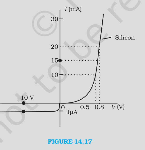
Figure 14.17 shows a typical characteristic for a silicon diode. In forward bias the current creeps up slowly and then rises steeply after a threshold, about 0.7 V for silicon and 0.2 V for germanium. In reverse bias the current is almost flat and very small until breakdown. The dynamic resistance, r d = ΔV/ΔI, is small in forward bias (typically 10 ohm) and enormous in reverse bias (typically 10 to the 7 ohm). The asymmetry is the whole basis of rectification.
5.5 Rectifiers
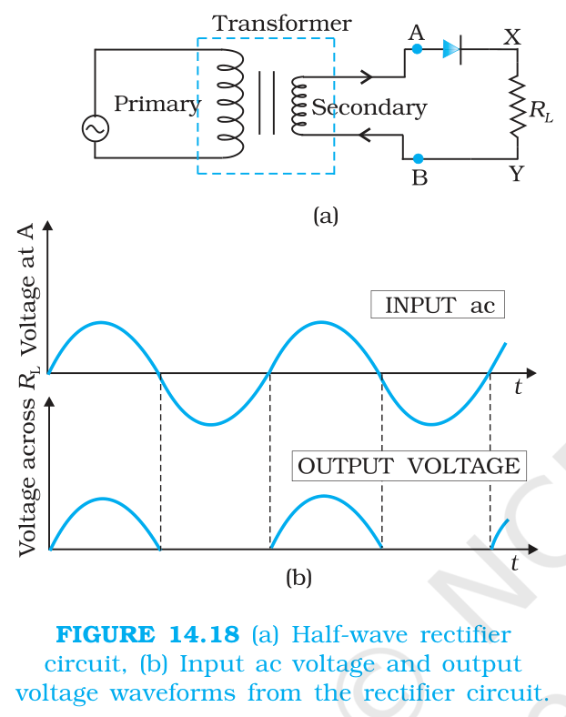
A half-wave rectifier puts one diode in series with the load across the secondary of a transformer (Figure 14.18). During the half cycle in which A is positive the diode conducts and the load carries current; during the other half cycle the diode is reverse biased and the current is negligible. The output is a series of pulses, one per input cycle, so the output frequency equals the input frequency.
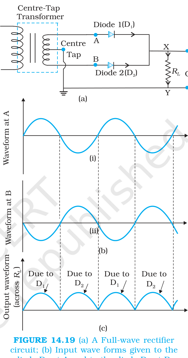
A full-wave rectifier uses two diodes and a centre-tapped secondary (Figure 14.19). The two diode p-sides connect to the two ends of the secondary, their n-sides join, and the output is taken between that common point and the centre tap. When A is positive with respect to the centre tap, D1 conducts; when B is positive, D2 conducts. Each diode handles half the cycle, but the two halves alternate, so the load gets a pulse in each half cycle and the output frequency is twice the input frequency. A four-diode bridge version does not need the centre tap.
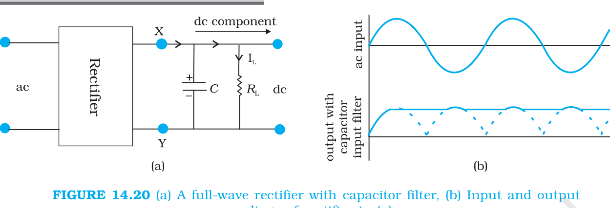
The pulsating output is unidirectional but far from steady. A capacitor connected across the load (Figure 14.20) acts as a filter: it charges up as the output rises, then discharges slowly through the load when the output falls. The discharge time constant is the product C times R L, so a large capacitor gives a nearly steady output close to the peak value. An inductor in series with the load can be used for the same purpose, and these added circuits are called filters.
5.6 Comparing the two rectifiers
The half-wave circuit is simpler but wastes half the input. The full-wave circuit uses the whole cycle and therefore gives a smoother output at twice the ripple frequency, which is easier to filter. The bridge version removes the need for a centre tap, at the cost of two more diodes and a slightly larger forward drop. In numerical questions, the frequency statement is what separates the two in the mark scheme.
Slideshow, slide 1 of 3. Use the left and right arrow keys to change slides and the space bar to play or pause.
A half-wave rectifier circuit with its input alternating voltage and the rectified output pulses across the load.
Exam
For rectifier questions always draw the circuit, the input waveform and the output waveform, and state the output frequency. For the diode characteristic, quote the threshold and the reverse saturation current before sketching. A common mistake is to call the reverse saturation current zero; it is small and nearly constant, not zero, and it is limited by the minority carrier concentration.